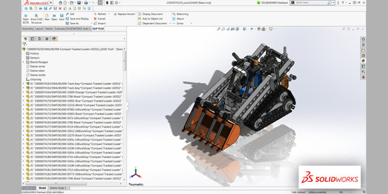


This just gets everything in a known position. Click move on the sketch toolbar and use from/to option to move all selected items from the point in the sketch to the (0,0) point in the drawing view.CRITICAL STEP: Select all the entities of the pasted sketch including your original desired (0,0) point from the sketch (not the new point you created in the drawing).Create a new point at (0,0) in the drawing view (create a point and set its coordinates to (0,0 in the properties panel on the left).Copy your sketch from the part and paste into the drawing view.MAKE SURE DRAWING VIEW AND SHEET SCALES ARE SET TO 1:1 Create a new drawing and do not show the sketch format.CRITICAL STEP : Create a point in the sketch at the location you want to be x=0 y=0 (unless there is already a corner or endpoint there in which case you can just use that item later).Delete the rectangle (you could optionally create the rectangle in a separate sketch for later reference.) You probably don’t want the rectangle left in this sketch unless you want to cut it with the laser also. If scale is important to your project, you need to keep track of these dimensions exactly. I usually draw a temporary rectangle and constrain it to be coincident or tangent and measure that. CRITICAL STEP : measure the XY bounding dimensions of the artwork to be cut in your sketch.Now you should have all your edges in the sketch On the sketch toolbar, click “project edges”.This should result in all the edges within the window select area being highlighted Window-select the whole part (or features you want to cut).Open the selection filter and click the “edges” selection filter (optional, but makes it easier to select all face edges including internal contours).Create a sketch on the face of your part.Maybe you share my pain? Here’s how to do it! I refer specifically to SolidWorks here, but the critical steps are common to most solid modeling programs such as Autodesk Fusion 360, OnShape, Creo, Inventor etc: I just spent a long time figuring out how to actually get design data out of CAD to cut on my Glowforge.


 0 kommentar(er)
